FPGA based Digital World
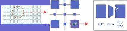
Welcome to FPGA based Digital World.
Analog circuit is the basis of electronics, and covers lots of area. |
Electric Circuit
Electric circuits interconnect electric elements (or electric devices) to accomplish the targeted task according to the application. A simple and a complex circuit are illustrated below.
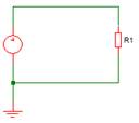
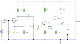
A Simple Circuit A Complex Circuit
Whether simple or complex, the circuit consists of electric elements and the interconnections.
Electric Elements
Two types of elements can be used in the circuit: active element and passive element. An active element (e.g., battery, generator or operational amplifier) is capable of generating energy for the circuit, acting as voltage or current source, while a passive element (e.g., resistor, inductor or capacitor) is not able to generate energy but usually consumes energy.
In this site, knowledge on electric elements including diode, bipolar junction transistor (BJT), field-effect transistor (or FET, including JFET, MOSFET, and MESFET) and operational amplifier (or OPA) will be introduced. The area covers the primary construction and characteristics, biasing configuration (for BJT and FET), amplifying circuit and its analysis or calculation, and the typical applications etc. of the above elements.
The voltage or current source can be divided into independent source and dependent (or controlled) source. A dependent source (e.g., VCVS, CCVS, VCCS, CCCS) is an active element whose quantity is controlled by another voltage or current, while an independent source is not. Typical circuit of current source will be touched in this site.
Power Supply as voltage or current source is quite important in an electric circuit. Low-voltage DC(lower than 36V) power supply is usually used in a circuit, it is usually transformed and rectified from a 220V AC mains supply. And the voltage also has to be regulated to meet the different voltages requirement (e.g., 5V for TTL component, 3.3V for CMOS component, 2.5V or 1.1V for FPGA,etc. ). The voltage can be linearly regulated or by switch mode. This site also introduces the regulation method.
For a MCU or FPGA, an important input signal is the clock, which can be sinusoidal or rectangular. PLL or DLL is usually embedded inside the MCU or FPGA to process signals from different clock domain, and the input clock signal is required to be stable and accurate. In this site, method to generate stable and accurate clock signal is also introduced.
Schematics Analysis
A device's schematics is usually very complex, and below steps help you to understand the device's schematics.
1 Functional overview
You need to know the device's function or requirement first: the target usage, the parameters to achieve,etc..
Then the input and output singals of the device are also to be explored, because each device can be viewed as a signal processing system.For this, the concepto of dataflow diagram in software analysis can be employed.
2 Functional decomposition
A device usually employs several functional parts to fulfill its target function, in parallel or in series.In this step, you try to find the subcomponents of the device.A block diagram helps you to organize the functions together.
Analog circuit and digital circuit employ different functional parts, but some parts are common, e.g., power supply.
For an analog circuit, it usually employs below parts except the power supply.
1) signal amplifying, e.g., voltage amplifying or power amplifying;
2) signal rectifying, e.g., filtering.
For a digital circuit, it usually has a main component such as a MCU or FPGA, and other parts are auxilary or interfaces to the main component. So, you find the main component first, and then find the auxilary components and their relationships.
3 Find the signal processging path
Analyze the signal paths from the input signals to the output signals.
4 Estimate the quantities of the device
With the above steps, you've analyzed the circuit qualitatively.
In this step, you'll analyze the circuit quantatively. The common quantatives include the power consumption, etc. It's usually estimated roughly, by simplifying the circuit.
And sometimes you need to analyze part of the circuit specifically, due to its importance.
In this case, you can choose one of below methods or both.
1) circuit analysis theorem and techniques mentioned here;
2) circuit simulation tools like PSpice, Simextrix, etc.
Circuit Analysis Theorem
Electric circuit theory and electromagnetic theory are fundamental for electrical engineers.
Two types of sources or signals are commonly used in electric circuit: one is called direct current or DC, the other one is called alternating current or AC (e.g., sine wave). Although named as (direct or alternating) current, it is also used in other terms, such as ‘AC voltage’ or ‘AC signal’, because whenever the current in the circuit alternates, so will the voltage.
The circuit can be analyzed in time domain (for transient response), frequency domain (for steady-state response) or s domain (for transient or/and steady-state response). In this site, knowledge on electric circuit analysis (e.g, Nodal analysis, mesh analysis, Thevenin’s theory, phasor, Fourier series, Fourier transform and Laplace transform in transfer function analysis ) will be introduced.
CAD tools are also useful for circuit analysis.
PSpice or Simetrix are popularly used to analyze the electric circuit, from time domain to frequency domain. Matlab is useful for analysis of the transfer function in an electric circuit.
EDA Tools
EDA tools are used to design the schematics and layout of electric circuit, and also for high-speed analysis.
Altium Designer(AD, derived from protel) is one of the popular EDA tools in universities. Meawhile,EDA tools from MentorGraphics(Siemens) are becoming more and more popular, and three software sets targeted at different usages are provided by Mentor: PADS(including DxDesigner, PADS Layout/Router, HyperLynx) for low-end usage, BoardStation and Mentor EE for medium to high end usage.
Tools for circuit analysis and degsign will also be introduced in this site.
| Altera/Intel | Xilinx | Lattice | Learn About Electronics |
| MircoSemi | Terasic | Electric Fans |
| All rights reserved by fpgadig.org |
| Electric Device |
| Diode |
| Bipolar Junction Transistor |
| Field Effect Transistor |
| Operational Amplifier |
| FPAA |
| Circuit Analysis |
| DC Circuit |
| Basic Laws |
| Basic Analysis Techniques |
| Linear Circuit |
| Analysis Theorem in Linear Circuit |
| AC Circuit |
| Sinusoidal Steady-State Analysis |
| Sinusoid and Phasor |
| Basic Laws |
| Analysis Techniques |
| Frequency Response |
| Non-Sinusoid Steady-State Analysis |
| Transient Analysis |
| First Order Circuits |
| Second Order Circuits |
| Two-port Networks |
| Related Knowledge |
| Waveforms in Electric Circuit |
| Power Supply |
| Linear Regulator |
| SMPS Basic Topology |
| SMPS with Transformer |
| SMPS without Transformer |
| Clock Generation |
| EDA Tools |
| Technical Notes |
| DC-DC Test |