
FPGA based Digital World
Welcome to FPGA based Digital World.
Analog circuit is the basis of electronics, and covers lots of area. |
Sinusoidal Steady-State Analysis
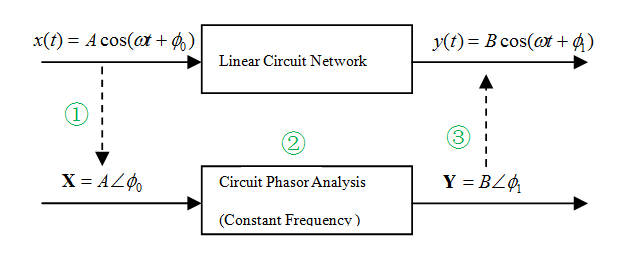
In a linear, time invariant(LTI)circuit, if the source is a sinusoid(steady-state), then phasor analysis could be employed.
The steps to analyze the AC circuit are with phasor:
1) Transform the sinuoid source to the phasor or frequency domain;
Epxress the source in cosine form(real part of the phasor):
v(t)=Vm*cos(ωt+Ф)
then the phasor form would be
V=Vm*exp(Ф)
2) Solve the problem in phasor doamin using the same techniques as in DC analysis;
The impedance or admittance of circuit element are to be expressed in phasor domain.
3) Transform the resulting phasor to time domain
The solution in time domain would be the real part of the resulting phasor(Vom*exp(Фo)), i.e.,
vo(t)=Vom*cos(ωt+Фo)
| Altera/Intel | Xilinx | Lattice | Learn About Electronics |
| MircoSemi | Terasic | Electric Fans |
| All rights reserved by fpgadig.org |
| Electric Device |
| Diode |
| Bipolar Junction Transistor |
| Field Effect Transistor |
| Operational Amplifier |
| FPAA |
| Circuit Analysis |
| DC Circuit |
| Basic Laws |
| Basic Analysis Techniques |
| Linear Circuit |
| Analysis Theorem in Linear Circuit |
| AC Circuit |
| Sinusoidal Steady-State Analysis |
| Sinusoid and Phasor |
| Basic Laws |
| Analysis Techniques |
| Frequency Response |
| Non-Sinusoid Steady-State Analysis |
| Transient Analysis |
| First Order Circuits |
| Second Order Circuits |
| Two-port Networks |
| Related Knowledge |
| Waveforms in Electric Circuit |
| Power Supply |
| Linear Regulator |
| SMPS Basic Topology |
| SMPS with Transformer |
| SMPS without Transformer |
| Clock Generation |
| EDA Tools |
| Technical Notes |
| DC-DC Test |