FPGA based Digital World

Welcome to FPGA based Digital World.
Analog circuit is the basis of electronics, and covers lots of area. |
Frequency Response of a Sinusoidal Circuit
A sinusoidal signal has three parameters: 1) amplitude 2)phase 3)frequency.
In sinusodial circuit analysis,
- If source frequency remains constant, phasor method is employed to find the ciruit's gain and phase behavior;
- If source amplitude remains constant, frequency response is employed to find the circuit's dynamic behavior as a function of frequency.
The frequency response of a circuit is the variation in its behavior wiht change in signal frequency.
Two methods are employed to describe the circuit's frequency response.
1) Transfer function
2) Bode plot
Transfer Function
The transfer function H(¦Ø) of a circuit is the freqeuency dependent ratio of a phasor output Y(¦Ø) to a phasor input X(¦Ø) of the circuit.
Note:
1) H(¦Ø) is a complex number with magnitude H(¦Ø) and phase §¶. -->Both the repsonse's magnitude and phase could be different from the input signals';
2) The input and output can be either voltage or current, but not power.
3) The frequency response of a circuit is the plot of the transfer function H(¦Ø) versus ¦Ø, with ¦Ø varifying from 0 to ¡Þ.
The transfer function can be simplified as
where, N(¦Ø) is the numerator polynomial part of H(¦Ø),
D(¦Ø) is the denominator polynomial part of H(¦Ø).
The roots of N(¦Ø)=0 are called zeros of H(¦Ø), expressed as z1, z2, ...;
The roots of D(¦Ø)=0 are called poles of H(¦Ø), expressed as p1, p2,...
Below seven types of different factors can appear in various combinations in a transfer function:
1 Gain K
Zeros
2 zero (j¦Ø) at the origin
3 Simple zero (1+j¦Ø/z1)
4 Quadratic zero
Poles
5 Pole 1/(j¦Ø)at the origin
6 Simple pole 1/(1+j¦Ø/p1)
7 Quadratic pole
They have different inflence to the frequency response and will be discussed in Bode plot.
Decibel Scale and Bode Plot
Bel is the ratio of two levels of power
Ratio in bel = lg(P2/P1)
and decibel(dB) is 1/10th of a bel
Ratio in dB = 10lg(P2/P1)
For a four-terminal network with input and output resistance to be the same, or for the same resistor, the ratio is
Ratio in dB = 20lg(V2/V1) = 20lg(I2/I1)
Bode plot is a semilogarithm plot, where
- X axis; lg(¦Ø)
- Y axis:
for magnitude: H(¦Ø) in dB = 20lg( H(¦Ø)), where H(¦Ø) = mag( H(¦Ø) )
for phase: in degree
as shown in below diagram.
Simetrix is a powerful tool to find the bode plot of a circuit.
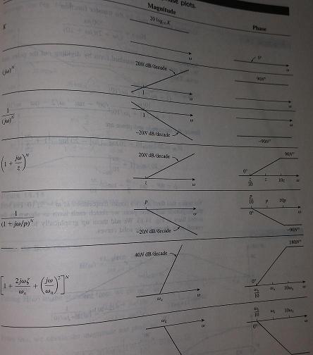
Bode Plot of Transfer Function
As mentioned in above, there're seven types of different factors in a transfer function.
Each factor can be ploted separately and then added graphically, because of logarithms involved.
The influence to the transfer function of each factor is to be discussed below, to help understand the theoretical analysis afterwards.
1 Constant gain K
Magnitude; 20lgK , Phase :0 degree
2 Zero at Origin(j¦Ø)
Magnitude: 20lg(¦Ø) , Phase :90 degree
A sample circuit is shown below.
Its transfer function is calculated as
H(¦Ø)= Vo/Vi = -j¦ØRC=-j¦Ø
3 Simple zero(1+j¦Ø/Z1)
Magnitude:
Phase:
A sample circuit is shown below.
The transfer fuction is
H(¦Ø)= Vo/Vi = -(1+j¦Ø)
4 Quadratic zero ()
Magtitude
Phase
It has a similar curve as the simple pole, but with a magnitude slope of 40dB/dec, and a phase slope of 90¡ã/dec.
5 Pole at Origin(1/j¦Ø)
It has a similar property as in type 2,but with diffent polarity in Y axis.
Magnitude: -20lg(¦Ø) , Phase :-90 degree
A sample circuit is shown below.
Its transfer function is calculated as
H(¦Ø)= Vo/Vi = -1/(j¦ØRC)=-1/(j¦Ø)
6 Simple pole(1/(1+j¦Ø/p1))
It has a similar property as in type 3,but with diffent polarity in Y axis.
Magnitude:
Phase:
A sample circuit is shown below.
The transfer fuction is
H(¦Ø)= Vo/Vi = -1/(1+j¦Ø)
7 Quadratic pole ()
Magnitude
Phase
Below is a summary of the transfer function curves.

[Summary]
1 Zero acts as a feedforward path to the circuit;
2 At zero, the magnitude is increased(+3dB) , and increases at the slope of N* 20dB/dec;And the phase is increased ( N*45¡ã);
3 At pole, the magnitude is dereased(-3dB) ,and decreases at the slope of N* 20dB/dec.And the phase is decreased( - N*45¡ã).
| Altera/Intel | Xilinx | Lattice | Learn About Electronics |
| MircoSemi | Terasic | Electric Fans |
| All rights reserved by fpgadig.org |
| Electric Device |
| Diode |
| Bipolar Junction Transistor |
| Field Effect Transistor |
| Operational Amplifier |
| FPAA |
| Circuit Analysis |
| DC Circuit |
| Basic Laws |
| Basic Analysis Techniques |
| Linear Circuit |
| Analysis Theorem in Linear Circuit |
| AC Circuit |
| Sinusoidal Steady-State Analysis |
| Sinusoid and Phasor |
| Basic Laws |
| Analysis Techniques |
| Frequency Response |
| Non-Sinusoid Steady-State Analysis |
| Transient Analysis |
| First Order Circuits |
| Second Order Circuits |
| Two-port Networks |
| Related Knowledge |
| Waveforms in Electric Circuit |
| Power Supply |
| Linear Regulator |
| SMPS Basic Topology |
| SMPS with Transformer |
| SMPS without Transformer |
| Clock Generation |
| EDA Tools |
| Technical Notes |
| DC-DC Test |