FPGA based Digital World
Welcome to FPGA based Digital World.
Analog circuit is the basis of electronics, and covers lots of area. |
Basic Analysis Techniques for DC Circuit
Two circuit analysis techniques are developed from the basic laws: one is nodal anlysis, which is based on a systematic appliation of KCL; another is mesh analysis, which is based on a systematic application of KVL.
The basic idea behind is to take node or mesh as a special element to decrease the number of equations, and as a result, simplifies the analysis.
Nodal Analysis
Nodal analysis is a general procedure used to find the node voltages as circuit variables.
A node is the point of connection between two or more branches.
The steps to determine the node voltages are:
1. Select a node as the reference node(called as ground, with zero potential)
2. Assign voltages v1,v2,... to the remaining n-1nodes (n-1 variables)
3. Apply KCL to the n-1 noreference nodes, and n-1 equations are established as a result;
4. Apply Ohm's law to each branch, to express the branch current in terms of node voltages;
And substiute the currents in the equations in step 2 with node voltages;
5. Solve the resulting simulatneous n-1 equations, and the n-1 node voltages are obtained.
In step 4, the equations are usually expressed in matrix to be solved easily.
Mesh Anlaysis
Mesh analysis is a general procedure to find the mesh currents as circuit variables.
A mesh is a loop which doesn't contain any other loops within it.
The steps to determine the mesh currents are:
1.Assign mesh currents to i1, i2,... the n meshes(n variables)
2.Apply KVL to each of the meshes, and as a result, n equations are established
3.Apply Ohm's law to each mesh, and express the voltage of the each mesh in the form of current.
As a result, the equations in steps 2 are n simutaneous equations with n mesh current variables.
4.Solve the equations in step 3 to get the mesh currents.
In step 3, the equations are usually expressed in matrix to be solved easily.
Nodal Analysis or Mesh Analysis?
When to decide using Nodal or Mesh technique, below factors are to be considered.
1 Nature of the network
The basic idea is to decrease the number of variables or resulting equations.
Mesh technique: network with many series-connected elements, voltage sources or supermeshes ->more number of nodes, less number of meshes
Nodal technique: network with parallel-connected elements,voltage sources or supernodes -> more number of meshes, less number of nodes
2 Required variables
Mesh technique: mesh currents required
Nodal technique: node voltages required.
Analysis with Matlab or Mathcad or Simetrix
The equations established with the above circuit analysis techniques are usaually much complex for a complex network, and it's hardly possible to solve it with hand, so CAD tools are usually employed.
Mathcad can be used to solve the equations in formulasm, and Matlab is good at the numerical solutions to the equations established during the circuit analysis.
Simetrix on Windows can simulate the whole circuit, with the voltages, currents and even the transfer function to be obtained.
An Eaxmple
[Problem]For below BJT circuit, calculate the output voltage Vo.Suppose VBE=0.7V, and β=250.
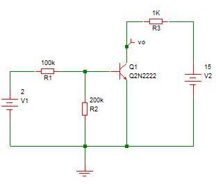
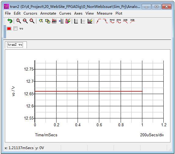
[Solution Method 1] Using Simetrix to solve it by simulation.
The output voltage curve is shown below.
[Solution Method 2] Using mesh analysis technique to solve it.
The circuit has 3 loops, as shown.
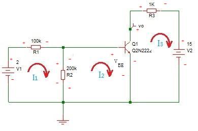
For loop 1,
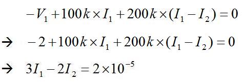
For loop 2,
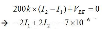
The above equations can be writen as
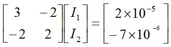
and it's solution is: I1=13 uA, I2= 9.5 uA
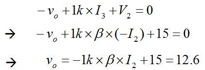
For loop 3,
[Solution Method 3] Using BJT equivalent circuit and nodal analysis technique to solve it.
The equivalent circuit is shown below.
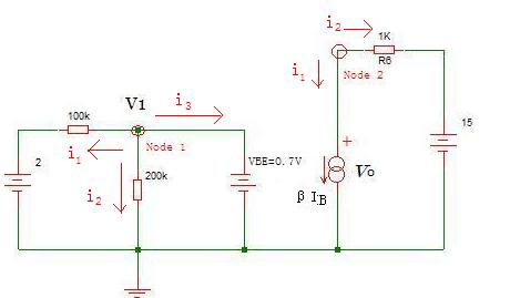
For node 1: V1=0.7V
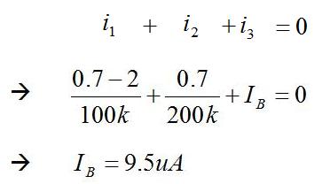
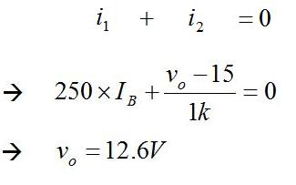
For Node 2:
Series Resistors and Votage Division
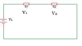
For series resistors shown in below figure, the voltage division on the resistors is
V1= Vi*R1/(R1+R2) , V2=Vi*R2/(R1+R2)
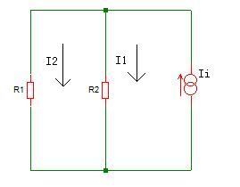
Parallel Resistors and Current Division
For parallel resistors shown in below figure, the current division on the resistors is
I1= Ii*R2/(R1+R2) ,I2=Ii*R1/(R1+R2)
| Altera/Intel | Xilinx | Lattice | Learn About Electronics |
| MircoSemi | Terasic | Electric Fans |
| All rights reserved by fpgadig.org |
| Electric Device |
| Diode |
| Bipolar Junction Transistor |
| Field Effect Transistor |
| Operational Amplifier |
| FPAA |
| Circuit Analysis |
| DC Circuit |
| Basic Laws |
| Basic Analysis Techniques |
| Linear Circuit |
| Analysis Theorem in Linear Circuit |
| AC Circuit |
| Sinusoidal Steady-State Analysis |
| Sinusoid and Phasor |
| Basic Laws |
| Analysis Techniques |
| Frequency Response |
| Non-Sinusoid Steady-State Analysis |
| Transient Analysis |
| First Order Circuits |
| Second Order Circuits |
| Two-port Networks |
| Related Knowledge |
| Waveforms in Electric Circuit |
| Power Supply |
| Linear Regulator |
| SMPS Basic Topology |
| SMPS with Transformer |
| SMPS without Transformer |
| Clock Generation |
| EDA Tools |
| Technical Notes |
| DC-DC Test |