FPGA based Digital World
Welcome to FPGA based Digital World.
Analog circuit is the basis of electronics, and covers lots of area. |
Second Order Circuits
A second order circuit is characterized by a second-order differential equation.It usually consists of two energy storage elements.
Natural Response of Source-Free Series RLC Circuit
A series RLC circuit is shown below.
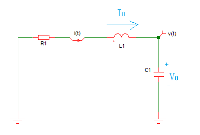
Suppose at t=0,
v(0) =V0,
i(0)= I0
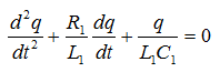
Applying KVL in the loop,
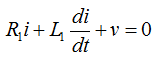
It can be rewritten as
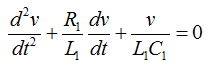
due to

Let

where A and s are contants to be determined.
And solving the probleme with below steps,
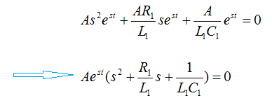
we get below characteristic equation.
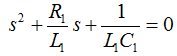
And the two roots of the above characteristic equation(also called natural frequencies, in Np/s) are
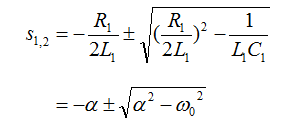
where

is the neper freqency or damping factor,
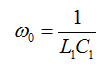
is the resonant frequency or stictly undamped natural frequency.
Finally, the natural response of the series RLC circuit is a linear combination of the two roots'solution, as below.
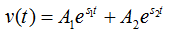
where A1 and A2 are determined from the initial values.
There're 3 types of solutions depending on the parameters of R,L and C, as depicted below.
1 Overdamped Case( )
)
In this case, both roots s1 and s2 are negative, and the response decays and approaches zero as t increases, as shown below.
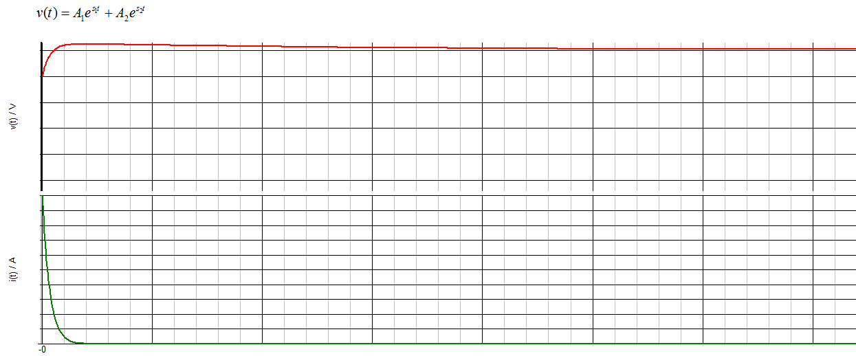 The initial current of the inductor and the initial voltage of the capacitor(or A1 and A2) determine the initial shape of the curve.
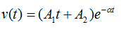
2 Critically Damped Case( )
)
In this case, the natural response is
3 Underdamped Case( )
)
In this case, the roots are written as
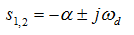
where
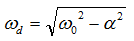
is the damped natural frequency.
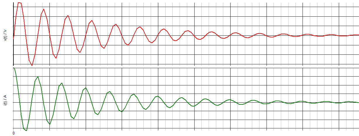
And the natural response is
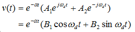
And an example curve is below.
Another method to solve the circuit is to rewrite the original equation as
since

And it has similar solution, but helps to understand the analog to the mechanical vibration system.
Step Response of Series RLC Circuit
For below circuit,
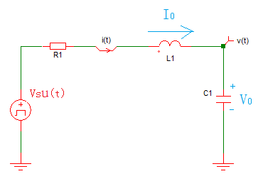
its step response is
where Vt(t) is the transient response, the same as in the natural repsonse of source-free one,
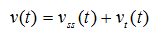
and Vss(t) is the steady-state response.
Steady-State Response of Series RLC Circuit to Sinusoidal Excitation
For below circuit,
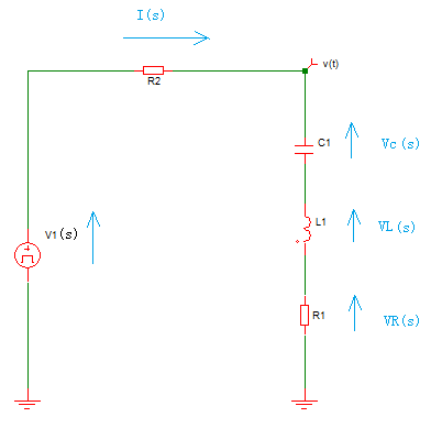
suppose V1(s) is a sinusoidal signal input, calculate the output voltage v(t).
In s domain,it could be calculated as
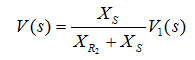
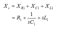
where Xs is the total impdedance of R1, C1 and L1,
Let's find its characteristics in frequency domain.
In frequency domain, the impedance becomes
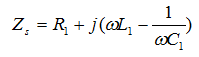
Clearly, the repsonse depends on the frequency.
When
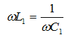
the imaginary part of the impedance becomes zero.And the frequency satisfying this condition is called the resonance frequency, where
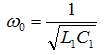 , rad/s
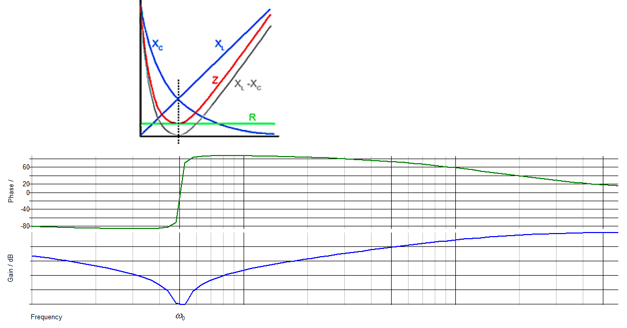
At resonance,
1) the series LC combination acts like a shortcut, and the impedance reaches minimum;
2) the voltage Vs and current Is are in phase;
3) the voltage across the inductance and capacitor can be much more than the source voltage(voltage magnification effect).
Because at resonance, the voltage across the inductance and capacitor are in anti-phase and equal in magnitude.
The frequency reponse is shown below.
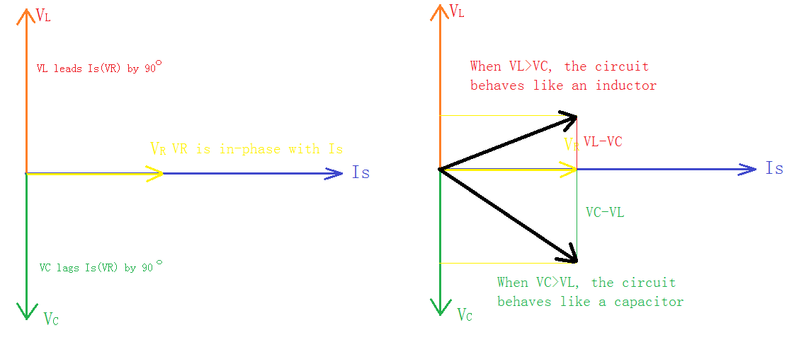
This can also be explained graphically in phasor domain.
Steady-State Response of Parallel RLC Circuit to Sinusoidal Excitation
For below circuit,
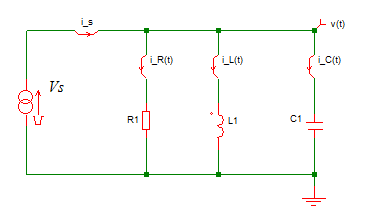
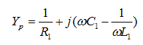
the admittance is
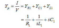
In frequency domain, the admittance becomes
So it has the same resonance frequency as in the series RLC circuit, i.e.,
At resonance frequency,
1) the LC combination acts like open circuit, and the admittance reaches minimum;
2) the voltage Vs and current Is are in phase;
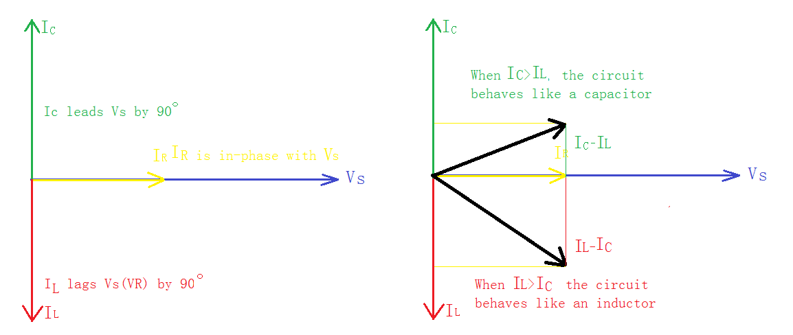
3) the current through the inductance and capacitor can be much more than the source current
The explanation in phasor domain is shown below.
Reference
1. Fundamentals of Electric Circuits(Fifth Edition), Charles K. Alxander and Mathew N.O. Sadiku, China Machine Press, 2013.2
2. LCR Parallel Circuits, www.learnabout-electronics.org
3. LCR Series Circuits, www.learnabout-electronics.org
| Altera/Intel | Xilinx | Lattice | Learn About Electronics |
| MircoSemi | Terasic | Electric Fans |
| All rights reserved by fpgadig.org |
| Electric Device |
| Diode |
| Bipolar Junction Transistor |
| Field Effect Transistor |
| Operational Amplifier |
| FPAA |
| Circuit Analysis |
| DC Circuit |
| Basic Laws |
| Basic Analysis Techniques |
| Linear Circuit |
| Analysis Theorem in Linear Circuit |
| AC Circuit |
| Sinusoidal Steady-State Analysis |
| Sinusoid and Phasor |
| Basic Laws |
| Analysis Techniques |
| Frequency Response |
| Non-Sinusoid Steady-State Analysis |
| Transient Analysis |
| First Order Circuits |
| Second Order Circuits |
| Two-port Networks |
| Related Knowledge |
| Waveforms in Electric Circuit |
| Power Supply |
| Linear Regulator |
| SMPS Basic Topology |
| SMPS with Transformer |
| SMPS without Transformer |
| Clock Generation |
| EDA Tools |
| Technical Notes |
| DC-DC Test |