
FPGA based Digital World
Welcome to FPGA based Digital World.
Analog circuit is the basis of electronics, and covers lots of area. |
Analysis Theorem in Linear Circuit
Several theorems and techniques have been developed to simplify the analysis of complex linear circuit networks,including superposition, Theveni's and Norton's theorems,etc.
Superposition
Superposition is a commonly used technology in circuit analysis, esp. in AC circuit analysis with source in sum of several harmonics.
Superposition principle states that, the voltage across or current through an element in a linear circuit is the algebraic sum of the voltage across or current through the same element caused by each source independently.
To apply superposition analysis, below steps help:
1 Keep only one source on, and turn off all others virtually;
For a voltage source, turn it off by short-circuit; while for a current source, turn if off by open-circutit.
2 Calculate the output voltage or current caused by the active source.
3 Repeat step 1 and 2 for other sources;
4 Add algebraically all the output voltages or currents contributed by each independent source, and the result is the final output.
In step 2, basic circuit laws may be employed.
[Example] Find the output voltage Vo in below circuit.
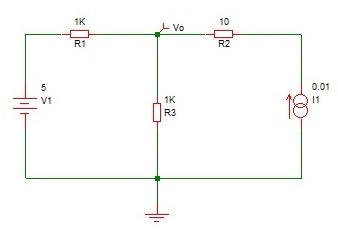
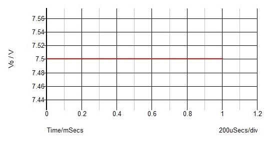
[Solution Method 1] Use Simetrix to simulate it, and the result is shown below.
[Solution Method 2] Use superposition method.
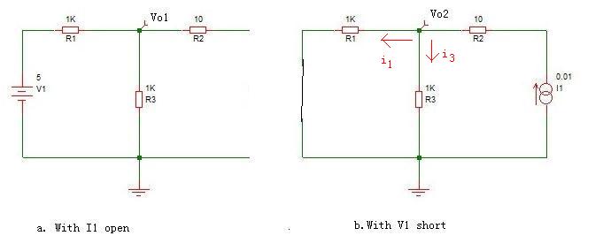
1) Set I1 open to calculate the contribution of V1 alone(as in figure a)
Using voltage division on series resistors
Vo1= V1*R3/(R1+R3)=2.5V
2) Set V1 short to calculate the contribution of I1 alone(as in figure b)
Using current division principle on parallel resistors, the current to R3 is
i3= I1*R1/(R1+R3) = 10mA*1k/2k=5mA --> Vo2=i3*R3=5V
So, the total output voltage of Vo=Vo1+Vo2=7.5V
Theorem of Equivalent Power Source
Sometimes only one brach or element of a complex circuit is to be analyzed. In this case, the ohter parts can be simplified as power source with the help of Thevin's theorem or Norton's theorem.
Two circuits are said to be equivalent if they have the same voltage-current relation at their terminal.
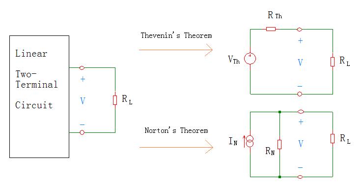
Thevenin’s theorem: any two-terminal linear network having several voltage sources and current sources can be replaced by a simple equivalent circuit consisting of a voltage source in series with a resistor followed by the load.
Thevenin’s voltage source(VTh) is equal to the open-circuit voltage across the two terminals of the circuit, and the Thevenin’s resistance(RTh) is equal to the resistance measured between the terminals with all the energy sources replaced by their internal resistances.
Norton’s theorem: any two-terminal, linear active network with current sources, voltage sources and resistors can be replaced by an equivalent circuit consisting of a single current source in parallel with a single resistor.
The current source (IN) is the short-circuit current between the two terminals of the network, while the resistance RN is the equivalent resistance measured between the terminals with all the energy sources replaced by their internal resistance.
Steps to apply Thevenin's theorem for DC Circuits
1.Remove the load under investigation(open-circuited),and obtain the voltage across the open-circuited path(as Thevenin voltage VTh);
In this step, basic laws and analysis techniques of circuit can be employed.
2 Keep the load under investigation removed(open-circuited), and turn off the independent sources.Then obtain the equivalent resistance of the network seen from the open-circuited terminals(as thevenin resistance RTh or Norton resistance RN);
3 Solve the problem of the load with Thevenin's equivalent voltage source acquired above.
It's normal if the thevenin resistiance obtained in step 2 is negative, which means that the circuit is supplying power from dependent sources.
Steps to apply Norton’s theorem for DC Circuits
1.Replace the load under investigation with a short circuit,and obtain the current throgh the short-circuited path(as Norton current IN);
2 Find Norton resistance RN with the same method in Theveni's theorem application step 2;
3 Solve the problem of the load with the Norton's equivalent current source acquired above.
In addition, the thevenin and Norton resistances are equal,i.e., RTh =RN.
And it's derived that: IN=VTh/RTh , and this is essential for source transformation.
Theorem of Maximum Power Transfer
A circuit network is ususally used to provide power to a load, and we expect to transfer maximum power to the load, in case of internal losses in the circuit.
The power transferred to the load is derivated as
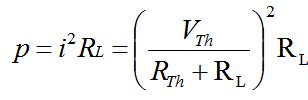
and shown below.
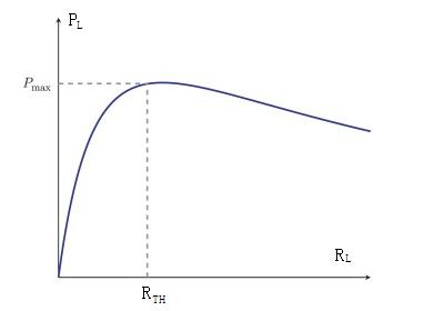
So, the maximum power is transferred to the load when the load resistance equals to the Thevenin resistance as seen from the load(RL=RTh).
| Altera/Intel | Xilinx | Lattice | Learn About Electronics |
| MircoSemi | Terasic | Electric Fans |
| All rights reserved by fpgadig.org |
| Electric Device |
| Diode |
| Bipolar Junction Transistor |
| Field Effect Transistor |
| Operational Amplifier |
| FPAA |
| Circuit Analysis |
| DC Circuit |
| Basic Laws |
| Basic Analysis Techniques |
| Linear Circuit |
| Analysis Theorem in Linear Circuit |
| AC Circuit |
| Sinusoidal Steady-State Analysis |
| Sinusoid and Phasor |
| Basic Laws |
| Analysis Techniques |
| Frequency Response |
| Non-Sinusoid Steady-State Analysis |
| Transient Analysis |
| First Order Circuits |
| Second Order Circuits |
| Two-port Networks |
| Related Knowledge |
| Waveforms in Electric Circuit |
| Power Supply |
| Linear Regulator |
| SMPS Basic Topology |
| SMPS with Transformer |
| SMPS without Transformer |
| Clock Generation |
| EDA Tools |
| Technical Notes |
| DC-DC Test |