FPGA based Digital World
Welcome to FPGA based Digital World.
Analog circuit is the basis of electronics, and covers lots of area. |
Sinusoidal Signal and Phasor
AC circuit is driven by a source voltage or current which is time-varying, usually in sinusoidal waveform.
Siusoidal Signal
Sinusoid is a signal in the form of sine or cosine function.
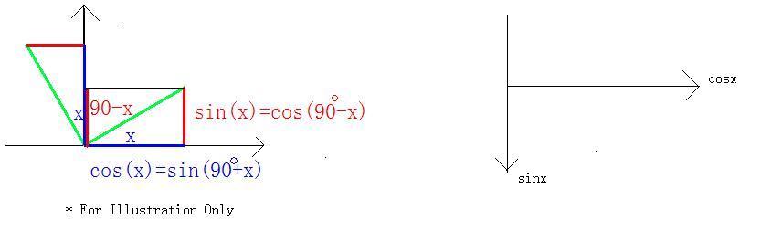
Sine wave and cosine wave can be transformed to each other, as listed below.
sin(x) = cos(x-90°), cos(x)=sin(x+90°)
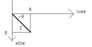
In addition, a sine wave and cosine wave can be added together to form another sinusoidal wave, and an example relationship is listed below.
Acos(x)+Bsin(x)= C cos(x-θ)
where, C=sqrt(A*A+B*b), θ=arctg(B/A)
And it could be also be estimated graphically below.
Phasor
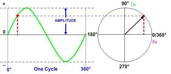
A sine or cosine wave is determined by it below parameters
- Frequency
- Amplitude
- Initial Phase
Once the above parameters are fixed, the wave is uniquely identified.
The circuit element usually changes the amplitude and phase when a voltage or current passes it. So, a term of phasor is used to describe both the amplitude and phase of a sinusoidal wave.
A phasor is defined as a combination of the amplitude Vm and phase Ф of a sinusoid.
V=Vm*exp(jФ) ,
where
V is the phasor representation of the sisusoid,
Vm is the amplitude and Ф is the phase.
Basically a rotating vector, simply called a “Phasor” is a scaled line whose length represents an AC quantity that has both magnitude (“peak amplitude”) and direction (“phase”) which is “frozen” at some point in time.
Relationship between Phasor and Sinusoid
The relation between a sinusoidal wave to a phasor is shown below.
v1(t)= Vm*cos(ωt+Ф)= Re(Vm*exp(jωt+Ф)) = Re( V*exp(jωt) )
v2(t)= Vm*sin(ωt+Ф)= Im(Vm*exp(jωt+Ф)) = Im( V*exp(jωt) )
So, a sinusoid can be regarded as a phasor multiplied by the time factor of exp(jωt), and then projected to the real or imagniary axis.
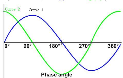
Since a phasor has magnitude and phase("direction"), it behaves like a vector, and can be represented in a phsor diagram.
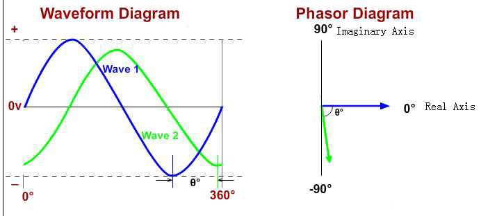
The relationship between a phasor and sinusoid can be expressed graphically below(projection on the imaginary axis, as sine wave. if the projection is on the real axis, then the wave is cosine wave).
Below is some example relationship between a time domain sinusoidal signal to a phasor or frequency domain representation.
Vm*cos(ωt+Ф) <--> Vm*exp(Ф)
Vm*sin(ωt+Ф) <--> Vm*exp(Ф-90o)
dv/dt <--> jωV
∫vdt <--> V/jω or -jV/ω
As you know, a complex number multiplied by j is to rotate the complext number counterclockwisely by 90o, while by -j is to rotate the complext number clockwisely by 90o. So, the dv/dt leads v by 90°,while ∫vdt lags v by 90°.
Please note:
1) Phasor V is not time-dependant, while v(t) is;
2) Phasor V is generally complex, while v(t) is real.
v(t) is the real or imaginary part of V, and is real.
Phasor Analysis
Phasor analysis can be used to convert calculus(integration and differentiation) operations into algebraic operations,as mentioned above.
Please note that
1)Phasor analysis only applies to sinusoidal signal;
2)Phasor analysis only applies to constant frequency;
3)Phasor analysis applies in manupulating two or more sinnusoidal signals only if they are of the same frequency;
In a linear, time invariant(LTI)system, there are four basic elements: arithmetic operators(+-*/), scale operation, differentiators, and integrators. Since sinusoidal frequency is not altered by these operations, if the input(s) to a system are sinusoids, then all signals in the system will be sinusoidal at the same frequency.
So phasor analysis can be used in LTI circuit analysis.
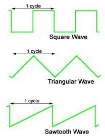
Extension Part - Waveforms in Electric Circuit
Sinusoidal wave is the basis of periodic waves, and is the important wave in AC circuit analysis.
Other frequently encountered curves in electric circuit are square wave,triangular wave and saw-tooth wave.
The harmanic series of these waves are to be discussed in Fourier series.
| Altera/Intel | Xilinx | Lattice | Learn About Electronics |
| MircoSemi | Terasic | Electric Fans |
| All rights reserved by fpgadig.org |
| Electric Device |
| Diode |
| Bipolar Junction Transistor |
| Field Effect Transistor |
| Operational Amplifier |
| FPAA |
| Circuit Analysis |
| DC Circuit |
| Basic Laws |
| Basic Analysis Techniques |
| Linear Circuit |
| Analysis Theorem in Linear Circuit |
| AC Circuit |
| Sinusoidal Steady-State Analysis |
| Sinusoid and Phasor |
| Basic Laws |
| Analysis Techniques |
| Frequency Response |
| Non-Sinusoid Steady-State Analysis |
| Transient Analysis |
| First Order Circuits |
| Second Order Circuits |
| Two-port Networks |
| Related Knowledge |
| Waveforms in Electric Circuit |
| Power Supply |
| Linear Regulator |
| SMPS Basic Topology |
| SMPS with Transformer |
| SMPS without Transformer |
| Clock Generation |
| EDA Tools |
| Technical Notes |
| DC-DC Test |