
FPGA based Digital World
Welcome to FPGA based Digital World.
Analog circuit is the basis of electronics, and covers lots of area. |
AC Circuit Analysis Techniques
Analysis techniques used in DC circuit also apply to sinusoidal phasor domain.
In this section, an example problem will be solved with different techniques used in DC anlaysis.
[Problem]
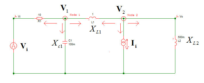
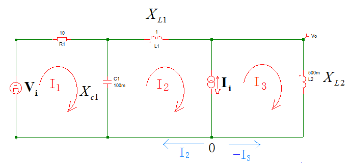
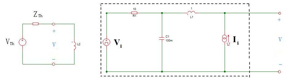
For below circuit,
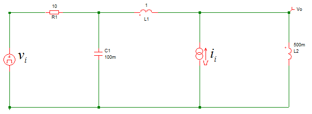
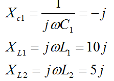
the input signals are as follows.
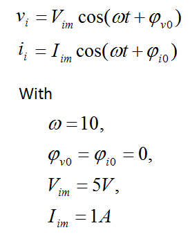
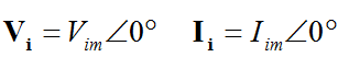
then, the corresponding phasors of the input signals are.
Calculate the output voltage Vo on L2.
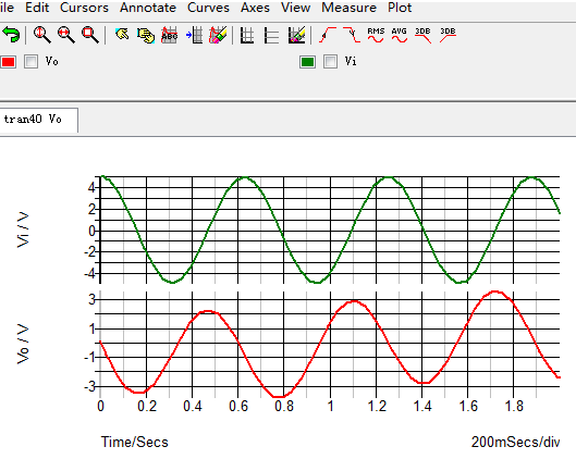
Simetrix Simulation
Use Simetrix to simulate the circuit to obtain the result as below.
Nodal Analysis
Nodal analysis is based on KCL, and KCL applies to phasor analysis, so Nodal analysis also applies to phasor analysis.
[Solution 1]
The circuit is divided into 2 nodes, as shown.
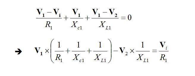
For node 1,
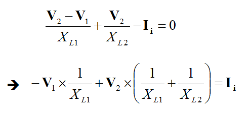
For node 2,
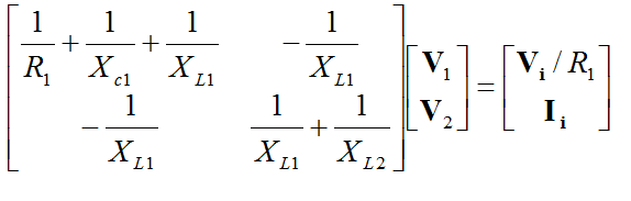
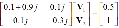
So, a matrix equation is obtained.
According to the precodition, we obtain
Then the matrix equation becomes
Mesh Analysis
Mesh analysis is based on KVL, and KVL applies to phasor analysis, so Nodal analysis also applies to phasor analysis.
[Solution 2]
Three meshes are included in the circuit, as shown.
From the diagram, it can be seen that Ii is between two meshes: mesh 2 and 3,so a supermesh is to be created by excluding the current source Ii, as shown below.
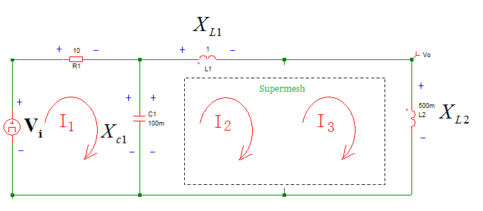
A supermesh results when two meshes have a common current source(independent or dependent),and KCL and KVL are both required to solve the circuit with supermesh.
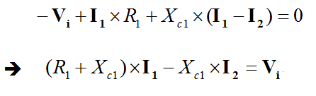
For loop1,
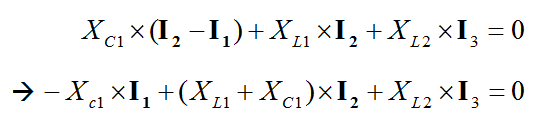
For Loop 2 and 3(supermesh),
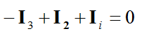
In addition, KCL is to be applied to the supermesh node 0 and we get
From the above 3 equations, the current I1,I2,I3 could be solved. And the the Vo is calculated as
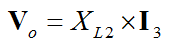
and the real part of Vo is the sinusoidal wave of the output signal.
Superposition Theorem
Note: in phasor domain, superpositon only applies to the same frequency. If the source signal consists of several frequencies, the repsonse of different frequencies should be analyzed separately in phasor domain, and added in time domain.
Thevenin's Theorem
[Solution 3] Solve the problem with Thevenin's theorem.
The Thevenin equivalent circuit is shown below.
1 calculate VTh with superposition theorem
With Ii off, the eqivalent circuit becomes
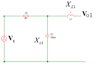
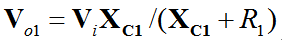
and Vo1 is calculated with series voltage division principle as
With Vi off, the equivalent circuit becomes
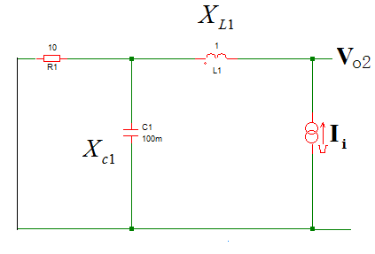
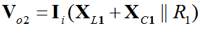
and Vo2 is calculated as
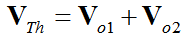
And the VTh is calculated as
2 calculate ZTh
With all independent sources off, the equivalents circuit becomes
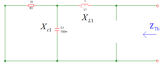
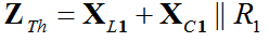
The equivalent impedance is calculated as
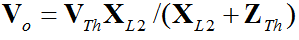
Then the output Vo is obtained as
Notron's Theorem
The Norton equivalent circuit is shown below.
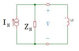
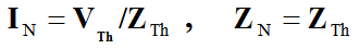
And IN and ZN could be calcuated from VTh and ZTh as below.
| Altera/Intel | Xilinx | Lattice | Learn About Electronics |
| MircoSemi | Terasic | Electric Fans |
| All rights reserved by fpgadig.org |
| Electric Device |
| Diode |
| Bipolar Junction Transistor |
| Field Effect Transistor |
| Operational Amplifier |
| FPAA |
| Circuit Analysis |
| DC Circuit |
| Basic Laws |
| Basic Analysis Techniques |
| Linear Circuit |
| Analysis Theorem in Linear Circuit |
| AC Circuit |
| Sinusoidal Steady-State Analysis |
| Sinusoid and Phasor |
| Basic Laws |
| Analysis Techniques |
| Frequency Response |
| Non-Sinusoid Steady-State Analysis |
| Transient Analysis |
| First Order Circuits |
| Second Order Circuits |
| Two-port Networks |
| Related Knowledge |
| Waveforms in Electric Circuit |
| Power Supply |
| Linear Regulator |
| SMPS Basic Topology |
| SMPS with Transformer |
| SMPS without Transformer |
| Clock Generation |
| EDA Tools |
| Technical Notes |
| DC-DC Test |